LED BLINK
Introduction
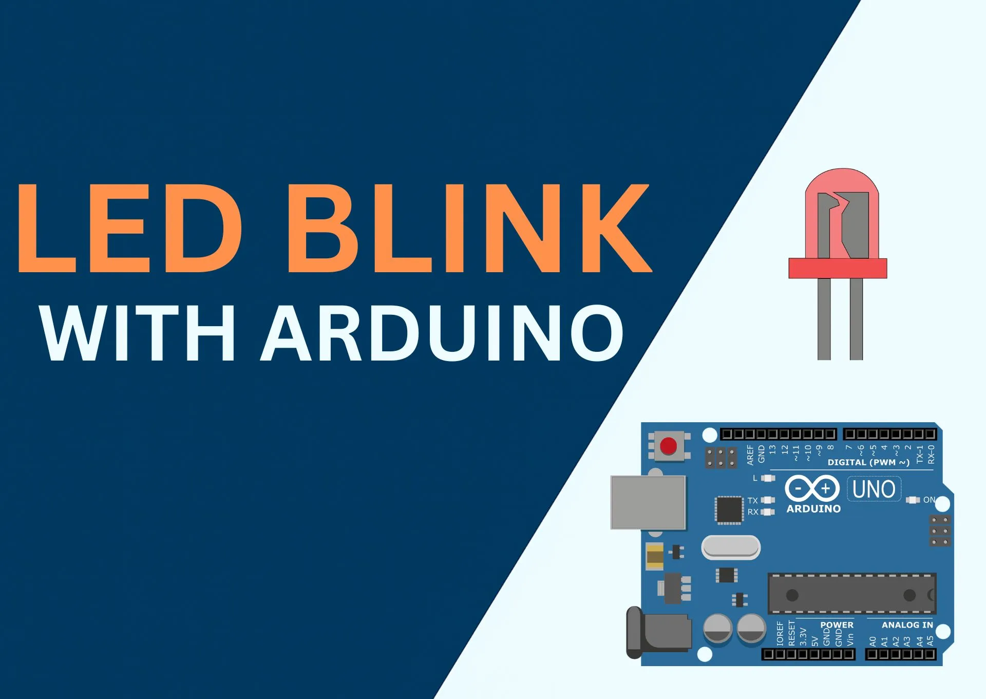
In this tutorial, you'll make an LED blink using Arduino UNO or ESP32 in under 5 minutes.
This is the classic first project that teaches how software controls real hardware using digital output pins.
What you’ll learn
- How digital output pins work
- How to safely connect an LED
- What
pinMode()anddigitalWrite()actually do - How changing delays affects hardware behavior
Bill of Materials
| S.Nr | Component | QuantityQTY | Link to BuyBuy |
|---|---|---|---|
| 1 | Arduino UNO R3or ESP32 DevKit | 1 | AmazonAliExpress |
| 2 | LED5mm, any color | 1 | Amazon |
| 3 | Resistor 220Ωnever skip — protects the LED | 1 | Amazon |
| 4 | Breadboardfull or half size | 1 | Amazon |
| 5 | Jumper Wiresmale-to-male | 4 | Amazon |
Circuit & Schematic
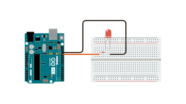
The circuit diagram shows physical connections.
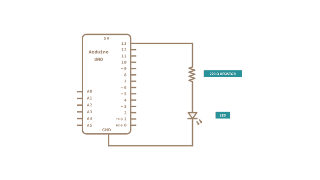
The schematic shows how electricity flows.
Wiring Instructions
- Insert the LED into the breadboard
- Connect a 220Ω resistor to the long leg (anode) of the LED
- Connect the other end of the resistor to digital pin 13
- Connect the short leg (cathode) of the LED to GND
- Plug your Arduino or ESP32 into your computer using USB
⚠️ Important
- If the LED is reversed, it won’t light up (this is safe)
- Never connect an LED directly to a pin without a resistor
See It In Action
The LED turns on for 1 second, then off for 1 second — on repeat.
Flash This Project Directly in Your Browser
No IDE · No drivers · No setup — just connect your board and go.
This project supports JustFlash — upload the firmware to your microcontroller in seconds using only your browser. Hit the button, select your COM port, and watch your project come alive. Zero code knowledge required for your first run.
Requires Chrome or Edge on desktop. Does not work on mobile or Firefox.
Arduino Code
This program turns the LED ON for 1 second and OFF for 1 second, repeatedly.
Block Diagram
The basic building blocks of the project — how power, the main unit, and the connected devices fit together:
Program Flow
A flowchart is great for explaining code logic. Here, setup() runs once, then loop() repeats forever — switching the LED on and off with a delay in between:
ESP32 + MQTT Connection
A sequence diagram is perfect for showing how devices talk over time — for example, an ESP32 publishing sensor data to an MQTT broker that a dashboard subscribes to:
//Prateek
//www.justdoelectronics.com

#include <LiquidCrystal_I2C.h>
#define BLYNK_PRINT Serial
#include <ESP8266WiFi.h>
#include <BlynkSimpleEsp8266.h>
#include <DHT.h>
LiquidCrystal_I2C lcd(0x27, 16, 2);

char auth[] = "uBTcT8j6LZTNPvcxkRg9Y";
char ssid[] = "JDE";
char pass[] = "par12345";

BlynkTimer timer;
bool Relay = 0;

DHT dht(D3, DHT22);
#define sensor A0
#define waterPump D5

void setup() {
  Serial.begin(9600);
  pinMode(waterPump, OUTPUT);
  digitalWrite(waterPump, HIGH);
  lcd.begin();
  lcd.backlight();
  dht.begin();

  Blynk.begin(auth, ssid, pass, "blynk.cloud", 80);

  lcd.setCursor(1, 0);
  lcd.print("System Loading");
  for (int a = 0; a <= 15; a++) {
    lcd.setCursor(a, 1);
    lcd.print(".");
    delay(500);
  }
  lcd.clear();

  timer.setInterval(100L, DHT22sensor);
  timer.setInterval(100L, soilMoistureSensor);
}

//Get the button value
BLYNK_WRITE(V7) {
  Relay = param.asInt();

  if (Relay == 1) {
    digitalWrite(waterPump, LOW);

  } else {
    digitalWrite(waterPump, HIGH);
  }
}

//Get the soil moisture values
void soilMoistureSensor() {
  int value = analogRead(sensor);
  value = map(value, 0, 1024, 0, 100);
  value = (value - 100) * -1;

  Blynk.virtualWrite(V8, value);
  lcd.setCursor(0, 0);
  lcd.print("Moisture :");
  lcd.print(value);
  lcd.print(" ");
}

void DHT22sensor() {
  float h = dht.readHumidity();
  float t = dht.readTemperature();

  if (isnan(h) || isnan(t)) {
    Serial.println("Failed to read from DHT sensor!");
    return;
  }

  lcd.setCursor(0, 1);
  lcd.print("T:");
  lcd.print(t);

  lcd.setCursor(8, 1);
  lcd.print("H:");
  lcd.print(h);
}

void loop() {
  Blynk.run();  //Run the Blynk library
  timer.run();  //Run the Blynk timer
}
How the code works
pinMode(13, OUTPUT)tells the board that pin 13 will control an output devicedigitalWrite(13, HIGH)sends voltage to the LED and turns it ONdelay(1000)pauses the program for 1 second (1000 milliseconds)
Try This
Change the delay value in the code:
delay(200);
- What happens when you make it smaller?
- What happens when you make it larger?
This is how you start learning by experimenting.
Common Problems
- LED not blinking → Check LED direction
- Nothing happens → Verify pin number and wiring
- Board not detected → Try a different USB cable
🚀 What’s Next?
- Blink using a different pin
- Control LED using a button
- Learn smooth fading using PWM
🤖 Tip: Ask the AI assistant to modify this code for PWM or button control.